Installing a NATO Receptacle
Most of the M-series vehicles were outfitted with the 2-pin style slave cable receptacle. However, if yours does not include the receptacle, don’t worry, we’ll show you how in four easy steps.
Most of the M-series vehicles were outfitted with the 2-pin style slave cable receptacle. However, after buying a 24-volt impact wrench and slave cable with the NATO ends, I felt compelled to install a matching NATO receptacle on the truck while retaining the old style receptacle on the rear of the cab on the passenger's side.
I found a NATO receptacle, with a removable plastic cover was purchased from TNJ Murray in Dover, Delaware, came from a generator and was just the right size to be located on any flat surface just about anywhere on the truck.
Here is the location I selected for the new receptacle. This location allows for easy access to the battery box connection.
A cab reinforcing support installed in conjunction with a ring mount was the existing receptacle was blocked unless the seats are removed along with the cab reinforcement plate on my truck. Therefore, I was looking for an alternate location.
I chose the vacant spot on the dashboard between the glove box and the door. The following list of tools and supplies will help make the complete installation:
1?2" pistol drill
1-3?4" hole saw
Drill bit
#2/0 welding cable (length to suit the location of the outlet to the battery compartment)
4 #2/0 compression lugs with a 3/8" hole (ring style)
8" Panduit heat shrink (stock number HSTT75-48-5C)
Compression tool for the lug (nice to have but not necessary)
NATO receptacle.
4 10-32 x 1" RHMS
Tywrap cable ties
Step 1
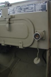
Once a suitable location for the receptacle is established, make the hole for the body of the receptacle using the hole saw and the 1?2" drill. Placing the receptacle in the new hole to locate and mark the four mounting holes to secure it in place for the 10-32 RHMS. Drill out the four mounting holes. It will be necessary to either notch the hole for clearance of the wire mounting bolts or connect them from the back as I did.
The mounting hole located on the dash with the round head machine screws installed. The screws were placed in from the back to allow using double nuts behind the receptacle for added clearance behind the dash. Before you select the location of the auxiliary receptacle check for clearance behind the dash.

Step 2
Attach one of the lugs to the end of the welding cable and compress it to the wire. If you prefer soldering the lug in place will also work. Place a short sleeve of the heat shrink tubing to cover the insulation of the wire and the barrel of the lug and using a heat gun or a torch carefully shrinking it evenly around the cable end. This step will be performed three more times.
Here is the positive terminal ready to be connected to the battery. Use extreme caution when working around the batteries as a connection between the positive terminal and ground can be hazardous.

Step 3
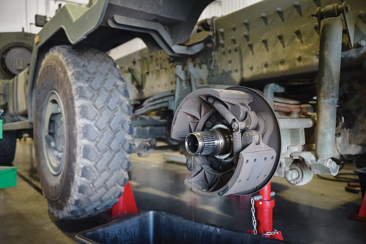
The receptacle has two 3/8" bolts to connect the two completed wire assemblies. Using a continuity meter, determine the bolt for the ground connection and install the ground cable. The other bolt will be for the 24-volt DC connection to the battery compartment. When measuring the cable, allow enough slack to allow the battery tray to side out. Connect both cables to the receptacle and mount it in place with the four 10-32 RMS screws.
This is the finished termination. A crimp tool is best to use but a vice grips and a blunt chisel can also crush the barrel of the lug.

Step 4
Attach the ground lug to a convenient location on the frame or other substantial metal area. Route the hot wire to the battery compartment drilling a hole if required and installing a rubber bushing to protect the cable. Connect the hot wire to the appropriate battery terminal and test for 24-volt at the receptacle. Using the wire ties, secure the cables in place.