In-the-Field Brake Job
Step-by-step by an active duty Marine by Mark Sigrist The need for brake work is usually proceeded by any number of indicators: spongy pedal, lack of pedal free play, free…
Step-by-step by an active duty Marine
by Mark Sigrist
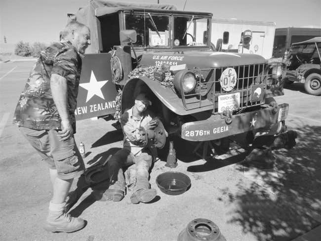
The need for brake work is usually proceeded by any number of indicators: spongy pedal, lack of pedal free play, free play to the floor, just not stopping in an appropriate distance, or metal-to-metal screeching in extreme cases. Prior to the 2017 Military Vehicle Preservation Association (MVPA) Route 66 Convoy, New Zealanders Boyd Mitchell and Peter Yates purchased a 1953 M37 Dodge 3/4-ton truck to drive cross country on the Convoy and then ship home to New Zealand. After driving the Dodge more than 2000 miles, they began to experience some of these brake issues.
During a Convoy rest day at our convoy rally point in a Walmart parking lot in Santa Fe, New Mexico, Mitch and Pete decided to dive into their on-board boxes of spare parts to change out the old brake pads and wheel cylinders.

They consulted with Ken Field, the Convoy Trail Officer about the job. Ken recruited the assistance of active duty U.S. Marine Corps Corporal W. Gunnar Sigrist, then on a two-week leave from the Corps to participate in his fourth MVPA convoy. Gunnar was a wheeled vehicle mechanic (officially, MOS 3521 Motor Transport Mechanic) assigned to Combat Logistics Battalion 7, stationed at the United States Marine Corps Air Ground Combat Center at 29 Palms, Calif.
Caveat
It is always a very good idea to follow the technical manuals (TM) to the letter. However, the instance described herein was an in-the-field job. Expedient methods, i.e., deviations from the TMs, were used due to lack of appropriate tools, materials, and timing.
Assessment
Gunnar’s first step was a visual check for any obvious defects: puddling or dripping fluid, seeping brake line connections, or possible holes in the lines. He followed with a check of the fluid level in the master cylinder. His third step was to chock the front wheels lift the rear axle to support the truck on jack stands. With the transmission in neutral, Gunnar spun the wheels by hand to check for drag and to visually check the inside of the wheel for egg-shaped or other obvious deformities in the brake drum. He found no issues.

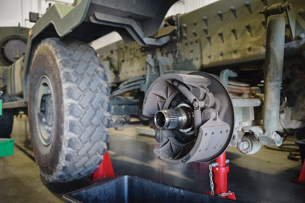
Pulling the Wheels & drums
Ken supplied a 3/4-inch drive Milwaukee electric impact wrench for Gunnar to pull the lug nuts and remove the rear two wheel and tire assemblies (caution: These are heavy). The next step was to adjust the two brake shoe cams. These are located behind the brake drum assembly and above the axle. These loosen the brake shoes by increasing the distance between the drum and brake pads.
Dodges have three counter-sunk drum-to-hub screws on each wheel. Sometimes, removal can be problematic due to rust. Luckily, in this case, all were easily removed.
Three drive shaft puller screws, if necessary, can be used to separate the brake drum from the hub. If the originals are lost, common bolts will work. When the drum pops loose from the hub, carefully pull it free and off – the dang thing is heavy so watch your toes and fingers.
An inspection of the drums did not reveal any scoring, cracks or deformities. Had this job been done in the shop, the drums would have been measured for size (thickness) and probably turned to remove brake shoe wear marks and make the interior contact surface absolutely round.

Removal of the brakes/cylinders
Gunnar removed the wheel cylinder inlet connection (brake line to cylinder) at the rear of the brake support/backing plate. He had an oil drip pan in place to catch the fluids as well as shop towels and absorbent pads available to catch spills.
No spring tool was available. So, Gunnar used a channel lock pliers and a bit of muscle to unhook the brake shoe return spring from the shoes. Then, he used a screwdriver to remove the two anchor bolt “C” clips and washers at the bottom of the backing plate below the hub. He set that aside to be used in reassembly.
After swinging the two brake shoes away from the spring retaining clips, heslipped them off of the bolts. This was followed by removing the two wheel cylinder-to-brake support mounting bolts and the cylinder was removed.


Clean it
Gunnar cleaned any dust, dirt, or errant POL from the brake drum and the hub/backing plate using a can of aerosol brake cleaner/degreaser. The new brake pads also received a shot of cleaner. Dirt and petroleum-based fluids are no friends of good brake performance.


Installation
Gunnar checked the new wheel cylinders. Many recent cylinders that fit this application are all the same. However, original equipment and some new production have different cylinders specific to the right and left side of the vehicle.
If the cylinders have a different sized bore on one end of the cylinder, install them with the “big in back,” that is, the larger bore towards the rear of the vehicle. Gunnar installed the wheel cylinder, making sure not to risk twisting off the studs by overtightening. He also was sure to install the new copper gasket washer when reattaching the brake line inlet connector.
Attachment of the wheel cylinder and brake shoes is in reverse order to their previously described removal process. Carefully slide on the brake drum over the brake shoes and hub. Murphy loves this part of the procedure and is always watching for the opportunity to mash a finger or even damage a brake pad. Seat the drum to the hub, align the screw holes, and apply the drum-to-hub screws making sure of a tight drum/hub fit. Mount the wheel and tire assembly.


Adjustment
Gunnar then spun the wheel while listening for brake drag. There was none.
The next steps were deviations from the TM protocols, specifically, using measurement tools. Gunnar adjusted the two upper brake shoe cams, one at a time, until a slight drag was heard/felt from the spinning wheel. He then backed off the adjustment until the drag ceased.
Then, he adjusted the lower two brake shoe heel anchor bolts, again one at a time, until there was a slight drag. Then he backed it off to permit free spin. The last adjustment step was to adjust the upper two cams. The target for the correct adjustment by this method is that instant when the apparent drag disappears.

Wash, rinse, repeat…
This operation was then repeated for the other three wheel/drums. Remember, safety first! Be sure to use the jack stands, chock blocks, and recover the released fluids. And don’t rush — that leads to errors and pinched flesh.
Bleeding the brake system
Now that the installation of the new parts was complete, it was on to filling the fluids. Many people dislike bleeding the brakes. In most cases, it is a two-person job. It can be painfully slow and a potentially oily situation.

Again, Gunnar was doing an in the field fix, so he did not have a hydraulic brake filler, nor a hose and jar to catch expelled fluid from the wheel cylinder bleeder screw (valve) as described in the TM.
He began by cleaning the area of loose dirt and debris to reduce potential of contaminates. Through the access plate on the driver’s side floor board, he remove the filler plug on the master cylinder.
From a fresh bottle of brake fluid (making sure it was a compatible fluid) Gunnar filled the master cylinder. He needed a small funnel with a long throat to reduce the spills.
Then, starting with the passenger side rear brake (the one furthest from the master cylinder), Gunnar opened the bleeder screw. He had an absorbent pad in place to catch any released fluid. Gunnar enlisted the author (his father) to slowly pump the brake pedal half way down and repeat until clear fluid free of bubbles flowed from the bleeder. He then tightened the bleeder screw and moved on to the driver’s side rear, the next furthest cylinder.

He repeated the procedure, followed by the front wheels. The master cylinder needed to be refilled from the supply bottle numerous times during the process. Gunnar had to even open a second bottle to complete the bleeding.
Discovering and diagnosing a flaw
After getting what looked like a good flow from all four wheel cylinders and with the master cylinder filled, the brake pedal would not hold a steady pressure. It would slowly sink to the floor. This was an indication of a fluid leak or that air remained in or was introduced into the system. Gunnar went through the whole procedure on all four wheels again. But, he got the same results.
He traced all of the brake lines and connections looking for any sign of leaks. He didn’t find any.

He then wanted to review my procedures for pumping the brake and filling the master cylinder with new fluid. He determined that I had not been filling the master cylinder often enough!I allowed a few bubbles of air to be introduced into the line between fillings, causing the problems.
We followed the bleeding protocols again. This time, I kept dribbling fresh brake fluid into the master cylinder. Success — the brake pedal stayed up under constant pressure.
Completing the job
There were several things to do before the all-critical test drive. Gunnar checked the brake pedal for free travel. “Free travel” is the distance between where the pedal is at rest in the fully released upward position and the point where noticeable resistance is felt in the downward movement of the pedal. This distance should be about 1/2 inch of free travel.
The amount of free travel is controlled by the length of the master cylinder piston rod. If there is a significant deviation from this distance, adjust the master cylinder piston rod by turning the rod to achieve the 1/2 inch. Note: Some folks prefer an inch or more of travel, but Gunnar recommends following the TM specifications.
Gunnar directed the cleanup and disposal of used materials and the pickup and cleaning of tools. Mitch and Pete retained the removed wheel cylinders and brake shoes.

Finally, Mitch and Pete took the M37 for a test drive. They returned with a thumbs up all around.
After the final tightening of the lug nuts on the wheels and a check of the master cylinder fluid level, the M37 was ready for Convoy 1st Gear — the designated time when the Convoy Commander initiates movement.
Notes regarding this job
*The in-the-field-brake job took about an hour-and-a-half. This was much longer than was probably necessary.
Why? Gunnar had more than enough “supervision” by helpful fellow convoyers. In addition, a flock of curious public was drawn to the bevy of historic military vehicles. They were fascinated to find a current US Marine busy performing serous mechanic duty on a historic military vehicle in a parking lot. The asked lots of questions and took a lot of photos.
*Master mechanic Ken Field supervised the job and was the authority on quality control — and a source of tools and supplies.
*Gunnar said that an M37 brake job is a heck of a lot easier than doing the brakes on an MTVR, the USMC 7-ton truck or the LVSR, the 22.5-ton heavy USMC 5 axle truck, both built by Oshkosh.
Addendum
The Kiwi M37 traveled the last 1,300 miles of the convoy without further brake adjustment and did not require any additional brake fluid. This was a bit unexpected as the drums had not been turned, so the pads needed a small amount of space to “wear-in.” Historic military vehicle operators should expect to check brake shoe adjustment and brake fluid levels several times following replacement to assure the brake system is within appropriate tolerances.
After the Route 66 Convoy, the M37 was loaded into a container and shipped to its new home in New Zealand. Six months later, Ken and I met up with Mitch’s M37 on the 2018 New Zealand 100th Anniversary Armistice Easter Convoy, a 3000-kilometer trip around the North and South Islands of New Zealand. No further brake adjustments were undertaken. That was a testament to a journeyman USMC mechanic’s successful job done “in-the-field.”
Mark Sigrist was a US Army Vietnam Veteran and a retired USDA Forest Service Forester and Wildland Firefighter. He was a historic military convoy enthusiast who lived his dream in north central Idaho, sharing the land with abundant wildlife and very few neighbors. Unfortunately, our dear friend Mark passed away on 2 August 2020, after a courageous battle against cancer.