

Final answers to final drives
When dealing with historic military vehicles final drives can be tough to understand, easy to neglect.
A “final drive” may sound to some like a trip in a hearse to a cemetery, but in automotive context it refers to a vehicle’s drive axles, often the rear axles on conventional two-wheel-drive vehicles, all the axles on all-wheel-drive vehicles, and/or the track driving mechanisms of vehicles such as tanks, bulldozers and half-tracks. Simply said, a final drive is what puts an engine’s power on the ground to make a vehicle move. The primary purpose of any automotive vehicle, whether civilian or military, is to move people and/or some kind of cargo from one place to another. In the case of military fighting vehicles, such as tanks, the purpose is to bring their firepower into battle. If one strips most automotive vehicles down to their bare essentials, one finds that all require about the same basic components to make them move, and these components usually consist of an engine, some way to transmit the engine’s power to the driving wheels (usually through a transmission which may include a transfer case) and generally a drive shaft or shafts to one or more axles. These axles are usually equipped with differentials and comprise the final drive to the vehicle’s wheels or tracks. Of course, a vehicle also needs components to be steered and stopped, as well as a place for the driver to sit while controlling it, but these are secondary elements.
To make a vehicle auto motive, it needs a self-contained power plant, along with an onboard fuel source. The very first automotive vehicles were powered by steam engines and needed both a fuel source of wood, coal or oil, as well as an onboard water supply to produce the steam to power the engine. Steam engines are called “external combustion engines” because the burning of fuel takes place outside the engine in a boiler. Steam engines can be either reciprocating (meaning they have pistons, connecting rods, a crankshaft and a flywheel) or turbine type engines. Turbine engines usually operate at high rpm, and, therefore generally require a gear reduction system for use in automotive applications. Turbine engines may also be internal combustion types, burning gasoline, kerosene or jet fuel. During the late 1800s and early 1900s, there were many electric-powered cars and trucks. Their propulsion, of course, was an electric motor, and their onboard fuel source were batteries. Most early electric vehicles were slow and had a very limited range before needing their batteries recharged, but since they were simple to operate and had no clutch or transmission, they became quite popular as “ladies’ cars.” While today’s electric vehicles are being touted as environmentally-friendly, many of their advocates seem to forget or ignore a basic law of thermodynamics, which states, “you can’t get something for nothing.” Simply said, it takes the same amount of energy to move an electric vehicle as it does for a comparable gasoline or diesel powered vehicle, and at present most of that energy still has to come from the burning of fossil fuels to charge their batteries.
Back to final drives: when I was eleven, an enterprising twelve-year-old friend of mine bolted a large electric motor to his wooden soapbox car. The final drive was accomplished through a V-belt and pulleys to one rear wheel, and the fuel source was a hundred-foot extension cord. We called this contraption the Death Racer because it took off like a bat out of you-know-where with the V-belt screaming and smoking. This provided about five seconds of absolute terror to its drivers before reaching the end of its cord and yanking it out of the outlet. I have no doubt that if provided with a sufficient length of cord our Death Racer would have earned its name. Fortunately, my friend’s dad came home just as we were combining all the extension cords in the house and preparing to make a longer run. Unlike an internal combustion engine, whether gasoline or diesel, a steam engine or electric motor provides almost full power and torque at any RMP and therefore doesn’t generally need a transmission or clutch. The top speed of a vehicle thus powered is usually limited by either the final drive ratio, or the mechanical aspects of its engine or motor. In the case of our Death Racer, the final drive ratio was probably less than 2:1. Most electric motors reach about 1750 rpm, so you might be able to imagine all the fun and personal injury, we could have had if my friend’s father hadn’t come home and stopped us.
For most wheeled vehicles and HMVs, there are four basic types of final drive gears within live axles. The Spur Bevel Gear was the first to be invented. Although a Spur Bevel Gear axle is very strong, it’s also quite noisy. The Spiral Bevel Gear was an improvement over the spur bevel gear, with the main advantage being less noise. The Hypoid Gear was an offshoot of the spiral bevel gear. Mechanically speaking, the only advantage of a Hypoid Gear is that it allows the drive pinion to be placed below the center of the bevel gear. This lowers the vehicle’s drive shaft to provide more body clearance and a lower vehicle silhouette. Although a Hypoid Gear is quieter than a Spiral Bevel Gear, it operates under much greater stress, which is why Hypoid Gear Oil was developed. The Worm Gear Drive is generally used only on heavy vehicles, although the French Peugot 403 cars had a Worm Gear final drive.
Internal combustion engines provide a relatively efficient powerplant for automotive vehicles. Their fuel source is generally an onboard tank of gasoline or diesel fuel, though it can also be propane, natural gas, hydrogen or similar fuels, and there have been instances where gasoline engines were rigged to run on the gasses of burning wood, coal or coconut husks. Gasoline engines may also burn alcohol, and diesels can run on vegetable oil. If one chooses to ignore the very serious matters of environmental pollution and global warming, it may be said that the internal combustion engine has so far been the most practical type of power for automotive vehicles. The main problem with internal combustion engines is simply that there are so many of them. An internal combustion engine doesn’t require a boiler or bank of batteries, and in some cases not even a radiator or liquid cooling system, which means that their power-to-weight ratio as well as its power-to-mass ratio is relatively efficient. This allows the majority of a vehicle to be devoted to cargo or passenger transport; which, of course, is a vehicle’s primary purpose.
A slight drawback to the internal combustion engine is that it only develops its full power and torque within a certain RPM range, and even though early gas and diesel engines were slow-turning, a transmission was still required to provide a lower gear ratio for starting, climbing hills or pulling and carrying heavy loads. A clutch was also needed to disconnect the engine from the drive train for startup and shifting gears. Also, a higher gear ratio was needed to keep the engine RPMs down once the vehicle was moving. Three-speed transmissions became the most common for passenger cars and light trucks, while a four-speed transmission with a very low first gear was best suited for heavier vehicles. As vehicle technology progressed and roads were improved, allowing higher speeds, more gear ratios were added to transmissions. The top speed of most vehicles is usually limited by their final drive ratio, because most transmissions, whether three, four, five, ten, fifteen, speed, etc., are direct drive (1:1) in top gear. In other words, in top gear a vehicle’s transmission output and driveshaft RPM is the same as the engine RPM. The exceptions are overdrive or compound transmissions where top gear equals higher drive shaft RPM than engine speed. Nevertheless, a vehicle’s top speed along with its lowest-gear pulling power is still usually determined by its final drive ratio.
There are basically two types of axles used on most conventional automotive vehicles. These are “live axles” and “dead axles.” A dead axle is typically a solid front axle. A dead axle carries part of a vehicle’s weight, and while it may also be a steering axle, a dead axle doesn’t transmit engine power to the vehicle’s wheels. Another example of a dead axle is a “tag-axle” on a three-axle truck… it’s there to carry some weight, usually on the rear of the vehicle, but not to drive the wheels. Some very early automotive vehicles used a final drive setup that wasn’t much different from our Death Racer. The rear axle itself was dead, and only one wheel was driven, usually via a chain and sprockets in place of our V-belt. A little later in history, both rear wheels were powered from one axle shaft. This is generally called a Plain Drive Axle and is virtually obsolete except for go-karts. The Plain Drive Axle worked for very slow speeds and unpaved roads, but there was no differential to compensate for the rear wheels turning at different speeds, such as when rounding a corner. Even with smooth solid tires that slipped a lot, something had to give and that something was often the axle shaft breaking. A considerable improvement was made by the invention of the differential and live final drive axle, though on many early trucks, such as the Mack AC, the differential was not on the axle itself but mounted above it on the vehicle’s frame. The load-bearing axle below it was dead, and the rear wheels were driven by chains and sprockets from a live shaft above. Although somewhat noisy, this setup worked well for heavy slow-speed vehicles.
For most wheeled vehicles in the HMV hobby there are three basic types of final drive axles and four basic types of final drive gears within those axles. Most common collectable HMVs are low-geared by today’s standards because they have relatively small engines and were designed for slogging through mud with heavy loads under combat conditions rather than cruising along a freeway. The Spur Bevel Gear was the first to be invented and in some cases the gears were external and not inside the axle housing. As already mentioned, although a Spur Bevel Gear axle is very strong, it’s also quite noisy. The Spiral Bevel Gear was an improvement over the Spur Bevel Gear with the main advantage being less noise. The Hypoid Gear was an offshoot of the Spiral Bevel Gear. Mechanically speaking, the only advantage of a Hypoid Gear is that it allows the drive pinion to be placed below the center of the bevel gear, and although a Hypoid Gear is quieter than a Spiral Bevel Gear, it operates under greater stress, which is why Hypoid Gear Oil was developed. Hypoid final drive gears are mostly used in passenger vehicles and some light trucks.
Moving on to final drive axles themselves, we have already covered the Plain Drive Axle (similar to a go-kart’s and otherwise obsolete) so let’s examine the other three basic types. There is the Semi-Floating Axle, which is still used on many passenger vehicles and light trucks. It was also used on late model CJ2A Jeeps, as well as some CJ3As, CJ3Bs, CJ5s and CJ6s. With this type of axle the vehicle’s weight is carried entirely on the end of the axle shaft. This subjects the axle shaft to stresses caused by turning, braking, skidding and the wobbling of a bent or out-of-balance wheel. Should the shaft break, the wheel would be lost. Next is the Three-Quarter Floating Axle. This is a better setup for heavier and off-road vehicles because the weight is carried by the wheel bearings and not by the end of the axle shaft. Three-Quarter Floating Axles may have a tapered end, or the end may be flanged, as on some M606s and M38A1 s. Nevertheless, the stresses caused by turning, braking, skidding, or a wobbling wheel are still carried by the axle shaft and if the shaft breaks the wheel will be lost. Many half-ton and a few older 3/4-ton trucks also use this type of axle, with either tapered or flanged ends. Last is the Full-Floating Axle. The vehicle’s weight is carried by two roller bearings and not by the axle shaft, which “floats” within the bearings. Thus the shaft could break, or even be re-moved, and the wheel would not come off. Additionally, the only stress on the shaft is the driving or braking torque from the engine. MBs, GPW jeeps and early model CJ2As used this type of rear axle. This setup is also used on most 3/4-ton and larger trucks; and most common HMV front drive axles are Full-Floating types, but with a provision for steering.
In regard to final drive care, it’s surprising how many people tend to ignore their vehicless’ final drive axles when it comes to service and regular maintenance. Many folks service and repack their vehicles’ front wheel bearings at regular intervals but never give a thought to the rear axles, at least until something breaks or they lose a wheel. At best, a lot of people merely remove the plug in their rear differential housings to check the oil level when performing a lube job, but never do more than add oil if needed. Many people have never serviced their rear wheel bearings or drained and flushed the differential and put in new oil. It’s a testament to how well most rear axles are built that they can go year after year with almost no service or maintenance. However, when they do finally fail, it’s often in a serious and spectacular way, and usually at an inconvenient time and place. One should service their vehicle’s rear axles and wheel bearings just as often as they service the front. If your HMV is a daily-driver, you should service its axles and wheel bearings on a yearly basis. Servicing the rear axles of most common collectable HMVs should only take a leisurely day.
This applies to most four and six-wheeled two-axle vehicles, such as Jeeps, WCs, M37s, M715s, M880s, CUCVs, HMMWVs and Chevrolet G506s. Three-axle HMVs, such as WC63s and deuces may take a bit longer, but the wheel bearings of most full-floating axles on larger trucks usually require less time and trouble to service than the semi-floating axles of smaller vehicles,since one generally doesn’t have to dismount the road wheels and tires from the brake drums and hubs. For large HMVs with dual rear wheels, a dual-wheel jack will be helpful, and you might be able to rent or borrow one. However, you can easily build something from two-by-fours and roller skates, or use a furniture dolly or hand truck to handle a set of dual-wheels. I’ve also used a pair of skateboards. In most cases, you should need only a basic set of tools, new gear oil of the correct type (consult your manual), wheel bearing grease, suitable solvent for flushing and washing parts and either a new differential gasket or a sheet of gasket paper to make one. For some HMVs, a wheel-puller and a hub nut wrench will make the job a little easier. Naturally, you will need a jack and sturdy blocks or jack stands to support the vehicle. As I often say, never use cinder-blocks, bricks or stones because they can suddenly crumble. The best way to start rear axle service is to drain and flush the differential housing. The vehicle should be driven first to warm up the oil for faster draining. Block the vehicle’s front wheels to keep it from rolling, then slip a suitable pan beneath the rear differential housing and remove the drain plug. Also remove the upper, or oil level, plug. Many Jeeps and small HMVs don’t have differential drain plugs, so you’ll have to remove the whole cover. Even if your vehicle does have a drain plug, you should remove the cover after draining to flush all the old oil and bits of metal out of the differential housing. Jack up the rear axle so the wheels are just off the ground and block it securely. Then put the transmission in neutral and release the parking brake so you can rotate the differential gears. Some HMVs, such as the M37, don’t have removable differential covers, which leaves one with the options of either removing the entire third-member or doing a thorough flushing with some sort of pump and hose, though you can always do a better cleaning job by removing the third-member. If you have a CCKW or other HMV with a split-type Timken axle, the only convenient option is to flush the housing as best as you can with a pump and hose. An alternate method—if you don’t feel like removing a third-member (or the axle is a split-type) -- is to reinstall the drain plug, fill the housing with solvent and rotate the gears by turning the drive shaft, either by hand or with the vehicle idling in its lowest gear. You should drain and refill the housing several times if using this method.
You will usually find small metal particles, which are generally the result of normal wear and nothing to worry about. However, large chips and/or obvious chunks of broken gears are cause for worry and it may be time for a differential rebuild or replacement.
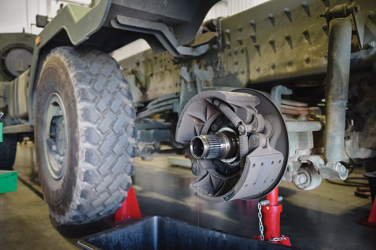
Most full-floating rear axles are easy to service and it’s usually not necessary to remove the wheels from the brake drums and hubs. Since the rear wheels are now off the ground, position the dual-wheel jack (or skateboards), if applicable, and remove the nuts from the axle flange. Some axles have tapered dowels on their studs, and these are easily loosened by a couple of light taps with a hammer on the studs. Some axles have convenient puller screws to start the flange, and their function is obvious. Once the flange is loose, pull the axle shaft from the housing. There may or may not be an oil seal on the flange depending upon the type of vehicle. There is also an oil seal inside the rear of the hub, which you will discover after removing the hub, brake drum and wheels from the axle. Replacing these seals is a good idea.
After removing the axle shaft, remove the two hub nuts. There is usually a locking tab between them, which will need to be straightened before you can take off the outer nut. A hub nut socket is the best tool to use, but most folks use a small chisel and hammer, despite the horror this seems to cause some purist mechanics.
After the nuts are off, one should be able to remove the hub, brake drum and wheel assembly from the axle spindle, and the other wheel bearing will come off with it. In some cases you may have to slacken the brake shoe adjusters so the brake drum will come off. Then remove the inner oil seal and wheel bearing. With care it’s possible to remove and reinstall the oil seal without damaging it, but again, it’s good practice to replace all seals.
Keep track of which is the outer and which is the inner wheel bearing, because they should always go back in their respective races. Clean everything thoroughly with the solvent of your choice. It’s very important to get all the old grease and oil off of everything so that it doesn’t contaminate or react with new grease. If you’re replacing a bearing, also replace its race.
After everything is cleaned and repacked, reassembly is basically the reverse of disassembly. After the hubs and wheels are back on the axle, install the axle shaft. Don’t forget the outer oil seal, if such a seal is used. With or without an outer oil seal, there is usually an axle flange gasket, which is easily made from gasket paper.
A lot of people use silicone instead of making or buying a new gasket, but I consider this a lazy practice. Besides, it seems silly to have a WWII vehicle with modern-day silicone instead of a proper gasket. Reinstall the differential housing cover, or the third-member, with a new gasket and Permatex, fill it with new gear oil and you’re done.
Service your vehicle’s final drive system on a regular basis, and you probably won’t end up having to search for a missing wheel along the road somewhere.
Like maintenance articles? Here are a few more for your reading enjoyment.