

Engaging Your Automotive Gauges
Knowing the basics of automotive gauges and senders can help keep your dash display alive and well.
I have two clocks; one doesn’t go at all, and the other loses a minute a day: which would you prefer? “The losing one,” you answer? Now observe: the one which loses a minute a day has to lose 12 hours, or 720 minutes before it is right again, consequently it is only right once in two years, whereas the other is evidently right as often as the time it points to comes round, which happens twice a day.” — Lewis Carol
One might ask the same kind of question about the instrument panel gauges in their historic military vehicle: is it better to have a gauge that gives inaccurate readings, or a gauge that doesn’t work at all?
Consider: at least you can trust the gauge that doesn’t work!
Most gauges in motor vehicles are there to protect the engine by warning the driver that something is wrong or going wrong. Therefore, does it make sense to have gauges that aren’t accurate or trustworthy? And while you can trust a gauge that doesn’t work, it is certainly not protecting anything!

There are basically five types of gauges commonly used in automotive vehicles. First, there are gauges that measure LEVELS of fuel, oil or other liquids. These may be either mechanical or electric. “Mechanical” or “electric” refers to what makes the gauge operate; meaning what moves the needle or pointer around or across the gauge’s face. This may be accomplished through a mechanical linkage of rods and gears, or by a monitored flow of electric current, electromagnetism, or electrical resistance, which is usually controlled by a rheostat, commonly called a sender.
Mechanical fuel level gauges are almost always located on or in a fuel tank, as on farm tractors, construction equipment, and early cars and trucks. This is because the complexity of their linkages makes them difficult to install in remote locations such as on a vehicle’s dashboard — with some exceptions, such as Model A Fords, in which the fuel tank was in the vehicle’s cowl directly in front of the dashboard. Many people are familiar with the type of mechanical fuel level gauges used in outboard motor tanks. Some old-time trucks and tractors also had mechanical gauges to measure the level of oil in the engine’s oil pan.
The second basic types of gauges measure TEMPERATURE. This may be the temperature of the coolant in radiators and engine blocks, or the oil temperature in engines, transmissions and differentials. Temperature gauges may also measure cylinder head, or exhaust gas temperature, such as pyrometers for diesel engines.
As with gauges that measure levels, temperature gauges may be either mechanical or electric. Mechanical types may be a simple glass tube thermometer, such as used on some vintage cars and trucks, or a Bourdon Tube device. Mechanical temperature gauges may be mounted directly on engines or machinery, or may be remotely located, such as in a dashboard, via a capillary tube. A temperature gauge may also be electrically operated, and there are several variations of these.
Thirdly, there are gauges that measure PRESSURE, such as engine oil, and air or hydraulic system pressure. A variation of pressure gauges are gauges that measure VACUUM, such as manifold vacuum in gasoline engines, or reserve vacuum in vacuum-boosted brake systems. As with other types of gauges, pressure gauges may be mechanical with Bourdon Tube movements, or may be electrically operated in several different ways. Both types of temperature gauges may be mounted directly on engines or machinery, or may be located on a dashboard or instrument panel. Mechanical vacuum gauges work on the same Bourdon Tube principle as mechanical pressure gauges, but vacuum gauges operate in reverse because vacuum “pulls” instead of “pushes.” This is why many vacuum gauges read counterclockwise instead of clockwise.
The fourth basic types of gauges measure or monitor ELECTRICITY. This may be either electrical flow or electrical potential, as with ammeters and voltmeters. It should go without saying that ammeters and voltmeters are always electrically powered, though there are both direct-reading and shunt-type ammeters.
The fifth types of gauges measure and/or count REVOLUTIONS, and are usually called speedometers and tachometers. These may be either mechanical or electric.


The first types of gauges -- the ones that measure liquid levels -- were also the first to be invented. Such gauges predated the use of electricity and were fitted to steam engine boilers to monitor the water level, though the earliest level-measuring gauges were around long before the steam age. The first gauge to measure liquid level was invented by one of our remote ancestors who wanted to know the depth of a stream before trying to wade across, and was simply a tree branch or spear shaft. When adventurers began to explore the seas, the stick gauge evolved into a sounding line and was marked with knots or pieces of cloth at intervals for easy reading. Other stick gauges were poked into jugs and barrels to measure the level of liquid inside. These types of gauges are still around, and there’s probably at least one on your vehicle... maybe two if it has an automatic transmission.

After the dipstick came the sight-glass. This can be a tube of glass, or a simple window into a tank, oil sump, fuel bowl or other reservoir. A sight-glass may also be used on tanks or boilers where internal pressure makes the use of a dipstick impractical. Like the dipstick, sight-glasses are still in use, and some early models of carburetors have them for monitoring the level in the fuel bowl. After the sight-glass came mechanical, then electrical gauges for measuring liquid levels.

The second type of gauge to be invented was the thermometer. Although there are many kinds of temperature gauges in use today, the simple glass tube thermometer is still used in marine and industrial applications. Visit an old car show and you will probably see this type of gauge on radiator caps and even mounted in dashboards. Temperature gauges may be either mechanical or electric.

The third type of gauge, the pressure gauge, came into use during the early days of steam because there had to be some way of monitoring the pressure inside a boiler. Today, there are both mechanical and electrically operated pressure gauges, though the basic design of the Bourdon Tube mechanical type hasn’t changed much.
Since the engines of most early cars and trucks didn’t have pressure lubricating systems, they didn’t need oil pressure gauges.
The fourth type of gauge was invented after electricity came into use, and is best known as an ammeter or voltmeter. Ammeters and voltmeters measure different things in an electrical system. Neither is really “better” than the other, they just give different information, and some vehicles have both.
The fifth type of gauge, to measure revolutions, also came into use during the steam age, first on steamboats and ships to monitor crank and propeller shaft revolutions, then on railroad locomotives to monitor speed. Most very early cars and trucks didn’t have speedometers because they couldn’t go fast enough for anyone to care. However, since speedometers and tachometers are not directly associated with monitoring an engine or vehicle’s mechanical or electrical health, they will be covered in another article.
For most cars and trucks anywhere in the world, the four standard gauges are ammeter, oil pressure, water temperature, and fuel level; though voltmeters have mostly replaced ammeters in newer vehicles and later M-series U.S. HMVs. This may be for economic reasons, since voltmeters are simpler and cheaper to install than ammeters. Still, there seems to be a universal agreement that these four gauges are the basic essentials for vehicle operation. Many people in the HMV hobby remember the late 1950s and early ’60s when Detroit tried to foist “idiot lights” on the American public as substitutes for ammeter and oil pressure gauges. For a few years General Motors even tried to convince buyers that idiot lights could also replace the temperature gauge with a green light for “cold,” a red light for “hot,” and nothing in between for normal. The implication seemed to be that the American motoring public was becoming too stupid to read numbers on a gauge.
For most cars and light trucks today, as well as most common U.S. HMV M-series military vehicles, all four basic gauges are electrically operated. An often-asked question is: Which is better, more accurate and trustworthy, mechanical or electric gauges? Not many decades ago, most mechanics and mechanically-minded drivers had few good words for electric gauges. While electric gauges, as with the clock mentioned at the beginning of this article, worked, they often gave vague or erratic readings... including the gauges of early M-series U.S. military vehicles. Today’s electric gauges are generally more accurate and dependable than those of the past; and electric gauges are easier to install than mechanical types on most modern vehicles because the entire instrument cluster is plugged in like a computer connection.
Still, many people prefer mechanical oil pressure and water temperature gauges in off-road or heavy-duty vehicles where accuracy and dependability are vital.
Of course, if one is restoring an M-series HMV, one will probably keep its stock electric gauges. There are ways to make these gauges more trustworthy, and one must also learn how to interpret their readings on their own vehicles.
Most common HMVs of WWII vintage have the four basic gauges of ammeter, oil pressure, water temperature, and fuel level. Many early WWII vehicles, such as the Chevrolet G-506, half-ton Dodges, and vehicles such as the White scout car and half-track, used civilian-style instrument clusters. While some of these vehicles retained civilian-style gauges throughout their production runs, others were standardized so their gauges were separate units, as on most Willys MB and Ford GPW jeeps. With a few exceptions, both the temperature and oil pressure gauges of most U.S. WWII tactical military vehicles were mechanical types with Bourdon Tube movements. Some vehicles, such as the WWII three-quarter-ton Dodge Carryall, often used by the Signal Corps for radio service, were fitted with a voltmeter in addition to an ammeter. This was because an ammeter and voltmeter monitor different aspects of a vehicle’s electrical system, and a voltmeter was essential for vehicles with radio gear. We will cover this when we get to ammeters, but now let’s look at the types of mechanical oil pressure and temperature gauges most commonly used on WWII HMVs.
A Bourdon Tube gauge is operated by pressure or vacuum. For an oil pressure gauge it’s the pressure of the oil being forced up a metal line or flexible hose from the engine that makes the curved Bourdon Tube try to expand against the tension of a small spring. The Bourdon Tube pulls on a link, which moves a gear mechanism, which in turn causes the needle or pointer to rotate around or move across the gauge’s face. The higher the pressure, the more the Bourdon Tube tries to expand, and the farther the needle moves around or across the gauge’s face. As the pressure lessens, the spring pulls the Bourdon Tube back into a tighter curve and the needle or pointer drops back down. Since the Bourdon Tube gauge operates by pressure or vacuum, it needs no electrical power. Nor does it matter whether the pressure is supplied by oil, fuel, water, air, or hydraulic fluid. Most mechanical oil pressure gauges in military vehicles are very accurate and long-lived. About the only thing that goes wrong is the Bourdon Tube will sometimes fracture from metal fatigue caused by decades of expanding and contracting. When this happens the gauge’s case usually fills up with oil so it’s obvious the gauge needs to be replaced. Air pressure or vacuum gauges will usually start hissing if the Bourdon Tube fractures.
These types of gauges are designed for specific pressure ranges, such as 0 to 60, 0 to 80, 0 to 100, etc. so using a 0 to 60 gauge on a system that runs 80 PSI can stretch or split the Bourdon Tube and/or strain the linkage and mechanism so the gauge loses its accuracy. While one can use a 100 PSI gauge, for example, on a system that runs lower pressure, a gauge designed for higher pressures may not be as accurate at registering lower pressures.
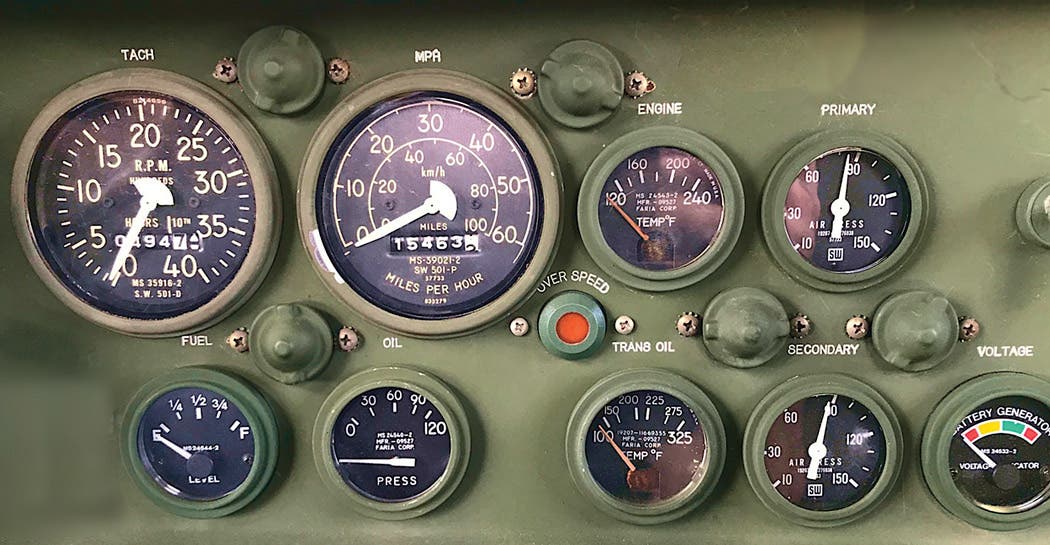
Generally speaking, most pressure and temperature gauges show the normal operating ranges for engines or components to which they are fitted as midway around or across the face of the gauge, and many instrument clusters are designed to be read at a glance in this fashion, with all needles mid-range indicating okay.
Most mechanical pressure gauges can be repaired or rebuilt: however, it is often more expense than it’s worth to repair an ordinary automotive or standard HMV gauge.
A mechanical temperature gauge also works by pressure, but in this case the pressure to operate the Bourdon Tube comes from the expansion of a gas, which is sealed within the capillary tube. Sometimes this gas is ammonia, or the tube may be partly filled with alcohol or benzene, which vaporizes to form the gas. But, other than this sealed capillary tube, the operation of a mechanical temperature gauge is same as mechanical oil or air pressure gauges. Most mechanical temperature gauges are also very long-lived and accurate. What usually goes wrong is that the capillary tube cracks from vibration fatigue and the gas or liquid leaks out. This type of temperature gauge can also be repaired — though, again, for most common HMVs replacing the gauge is usually cheaper than having it fixed.
Like mechanical pressure gauges, a mechanical temperature gauge uses no electrical power so it’s always “on.” This means that it will continue to show engine temperature when the engine isn’t running; and it’s normal for an engine’s temperature to rise a bit after shutoff, because coolant stops circulating through the radiator.

Ammeters were the first type of electrical gauge to be installed in motor vehicles, though very early cars and trucks with magneto ignition systems, hand cranks to start their engines, and no electric lights or accessories -- therefore needing no battery or battery charging system -- didn’t have ammeters. An ammeter is basically a little frame inside the case to which a permanent magnet is attached. The frame also supports a tiny armature, or shaft, and the needle or pointer is fixed to one end of this shaft so it can swing back and forth across the gauge’s face. The purpose of the permanent magnet is to keep the needle centered. On the back of an ammeter’s case are two terminals, and wires from the vehicle’s electrical and battery charging system are attached to them. When electric current flows out of the battery -- such as when a vehicle’s headlights are turned on without the engine running -- it passes through the ammeter. This flow of current acts as an electromagnet and is stronger than the permanent magnet so it attracts the armature in the direction of flow. This moves the ammeter’s needle toward Discharge or “-,” showing that current is flowing out of the battery. The stronger the current flow, the farther the needle is pulled across the ammeter’s face. When the flow of current stops, the permanent magnet returns the needle to center.
Inversely, when current flows into the battery -- from the generator or alternator when the engine is running -- the ammeter’s needle is attracted in the opposite direction toward Charge or “+.”
It should be noted that, because of the way most ammeters are built, the needle actually points in the opposite direction of the current flow. One might never need to know this unless they are installing or replacing an ammeter. If so, make sure the wires are connected to the correct terminals or the ammeter may read backwards. This won’t hurt anything, but could bring critical remarks from observers.
If one is installing an accessory, such as a radio or a spotlight, and isn’t sure which ammeter terminal to connect the wire to, use a test lamp to find which terminal makes the ammeter needle show Discharge or “-” when the lamp lights up.
There are two types of ammeters used in most common collector U.S. HMVs. The first is the direct-reading ammeter just described. Most WWII U.S. HMVs have this type, and it should be apparent from the size of the two main wires that almost all of a vehicle’s electrical power flows through a direct-reading ammeter. The usual exceptions are the starter, which draws so much current that it can’t be routed through an ammeter, and sometimes a vehicle’s horn.
The second type of ammeter is the shunt-type. It functions like a direct-reading type, except that instead of all of a vehicle’s current flowing through it, only a small portion is shunted through it. The main advantage of a shunt-type ammeter is that its wires can be smaller, making installation easier. The shunt-type ammeter is also better suited to an M-series vehicle’s waterproof electrical system. However, a shunt-type ammeter may not be as accurate as a direct-reading type because it only reads a small percentage of the actual current flowing through the system. Generally speaking, only early model U.S. M-series vehicles had ammeters. Later vehicles had voltmeters, and many early M-series vehicles were retrofitted with voltmeters during their military service.
Although an ammeter is electrically operated, it draws no power itself and is “on” all the time no matter if the ignition switch is on or off. This might be useful to know if one is working behind the dashboard, because the ammeter’s terminals are always live unless the battery is disconnected. So don’t wear watches or rings when sticking your hand behind the dash. An ammeter is pretty tough, and it’s hard to damage one with anything less than a hammer. Even “pinning” the needle with too much current (such as causing a short with your watch or ring) generally causes no harm, except to your finger or wrist. Tapping the ammeter’s case with a fingertip or screwdriver handle will usually flip a pinned needle back to center again… though an ammeter needle that’s been pinned too often will sometimes stay inclined in one direction. The ammeter may still work all right, but may be cosmetically unacceptable. Replacing such an ammeter is probably the simplest thing to do, though with some patience and skill one can usually take it apart and gently bend the needle so it reads on-center again. As with all electric gauges, the best way to assure accuracy and long life is to keep its connections clean and tight. This goes double for M-series HMVs.
As mentioned earlier, ammeters and voltmeters measure different things in a vehicle’s electrical system. An ammeter measures CURRENT FLOW in amperes while a voltmeter measures ELECTRICAL POTENTIAL in volts. One could say that a voltmeter monitors a vehicle’s potential electric power, whether that power is being stored in the battery when the engine isn’t running, or supplied by the generator or alternator when the vehicle is being driven. A 6-volt battery stores and therefore has the potential of supplying 6 volts for a vehicle’s electrical needs. Likewise, a 12-volt battery stores and supplies 12 volts, and a 24-volt system -- which usually has two 12-volt batteries connected in series -- stores and supplies 24 volts. So, in a 12-volt system, 12 is the magic number and is what should be maintained. If the voltage drops much below 12 volts, the vehicle’s lights will be dim and/or the vehicle may not even start. On the other hand, if a vehicle’s charging system malfunctions and starts pumping out 16 volts or more, the water will boil out of the battery, the battery’s plates may warp -- the battery may even explode -- and the vehicle’s lights will shine like carbon-arcs — for a very short time — while other electrical accessories such as radio gear may be damaged. An ammeter can only warn of such a malfunction by showing a constant charge long after the battery should have been fully charged -- such as on a road trip -- and an alert driver will spot this problem.
In U.S. M-series military vehicles, a voltmeter is often labeled a BATT-GEN (Battery-Generator) indicator, meaning that when the engine isn’t running the gauge shows the charge condition of the battery on the BATT section of the gauge face... which for most M-series vehicles is ideally 24 volts. When the engine is started and the generator or alternator begins charging, the voltage in the system rises to around 26-28 volts, which is shown on the gauge’s GEN section.
A 12-volt battery can only store 12 volts. A 6-volt battery can only store 6 volts, and a 24-volt system can only store 24-four volts with its two 12-volt batteries in series, so any extra volts will be lost when the engine is shut off, though what is commonly called a “surface charge” of a few extra volts may remain for a short time.
In most vehicles with 6-volt systems, the voltage with the engine running should not rise much above eight volts. In a 12-volt system, the voltage shouldn’t rise above fourteen volts; and twenty-eight volts is about safe top for a 24-volt system. Maintaining the ideal voltage range is the job of a voltage regulator on most generator and early-style alternator-equipped vehicles, while newer alternators are self-regulating.
To recap, a voltmeter shows both the charge condition of a vehicle’s battery when the engine is off, as well as whether or not the vehicle’s charging system is maintaining the correct voltage range when the engine is running. Unlike an ammeter, a voltmeter does not monitor how much current is flowing, either in or out of the battery, or though a vehicle’s electrical system. One might say that a voltmeter only shows whether or not a vehicle’s battery is fully charged, being properly charged, is being overcharged, or is not being charged and going dead.
On the other hand, an ammeter shows -- by flicking to Discharge or “-” -- if a vehicle’s charging system stops working. An accurate ammeter also monitors how much current is being drawn by a vehicle’s headlights, parking or blackout lights, radio, heater, etc. An ammeter also shows the rate of charge. For example, it might show 30 amps of current flow just after startup when the charging system is replacing the stored battery power used by the starter. Then it would gradually taper off to maybe 15 amps, and then less as the vehicle is driven and the battery becomes fully charged again. Finally, the ammeter’s needle would stay about centered or just slightly in the Charge or “+” position depending upon how accurate it was.
A voltmeter shows the charge condition of a vehicle’s battery when the engine isn’t running... something an ammeter can’t do. This is why voltmeters were installed on some WWII MVs for radio service. In this application they showed when the engine needed to be started to charge the battery after a period of transmitting.
Early M-series voltmeters had numbers, most newer models simply have color ranges: usually red, yellow and green. It would probably take a dedicated restorer to track down exactly when the changeover took place from ammeters to voltmeters -- late 1950s, early 1960s -- and, as forementioned, retrofits were common.
One should also be aware that the shunt-type ammeters of early U.S. M-series vehicles give rather vague readings, so one might be better off doing a retrofit to a voltmeter if a vehicle is used for more than just show.
Unlike an ammeter, a voltmeter uses a tiny amount of electric current to function. Although this power draw is very small, it can eventually run down a vehicle’s battery if the vehicle isn’t being operated, which is why most voltmeters are connected to the ignition switch and are turned on only when the engine is to be started. Voltmeters are usually very long-lived. They generally either work or they don’t, and should be replaced if they don’t. As with all electric gauges, one should keep their connections clean and tight. One can check the accuracy of a vehicle’s ammeter or voltmeter by comparing it to the readings of a test instrument such as a multimeter.
For vehicle restorations, one should be aware of slight differences in face markings and needle styles — usually between AC and Stewart-Warner gauges — in most common hobbyist U.S. HMVs. For example, in M-series vehicles, AC gauges usually have needles that are rounded at the tip, while Stewart-Warner needles generally have square tips. However, both types of gauges were used interchangeably, so there probably isn’t any “correct” type for specific vehicles, though most M-series vehicles came from their factories with all gauges matching in type. Like M-series speedometers, some early M-series gauges came with radium face markings and/or needles so they would glow in the dark. It is not a good idea to open up these gauges unless one likes the idea of breathing radioactive dust.
Most common U.S. HMVs don’t have mechanical fuel level gauges so there isn’t any sense in discussing them here. There are several different types of electric fuel level gauges. Some operate by resistance, some by voltage regulation, some by monitored amperage, and others by thermodynamics — the heating and cooling of bimetallic strips or coils. However, for the majority of people who work on their own vehicles, the most useful thing to know about electric gauges -- whether fuel, pressure, or temperature -- is that they have two main components. The first is the gauge itself on the instrument panel, and the second is the sending unit or sender. For electric fuel gauges, the sender is generally in the fuel tank, while the senders for electric oil pressure gauges are usually on the engine block, threaded in like a fitting. The senders for electric temperature gauges are generally on the engine’s cylinder head, water outlet to the radiator, or the upper part of an engine block, and also usually threaded in.
The second most useful thing to know about electric gauges is that the gauge and the sender must be compatible — and usually made by the same manufacturer. If not, the gauge and/or sender may either be damaged or simply won’t work.
One of the most common types of fuel gauges used in U.S. HMVs is the AC. The sender is a rheostat, and variations in resistance caused by the changing level of fuel in the tank as it raises or lowers a float make the gauge’s needle move across the face from Empty to Full, or vice-versa. There is a damper built into the gauge to prevent the needle from swinging wildly back and forth as the fuel in the tank sloshes around. The AC uses one wire from the sender in the fuel tank to the gauge on the dashboard, while another wire comes from the ignition switch to turn the gauge on or off. When hooking up a fuel gauge, DO NOT get these two wires confused or you may burn out the gauge or the sender, or both.
Another type of electric fuel gauge is the Autolite. This is a thermostatic type. Like the AC, the sender is a rheostat controlled by a float in the fuel tank. However, the Autolite gauge operates by the raising or lowering temperature of bimetallic strips within the gauge itself; that’s what moves the needle. Because this heating and cooling is a relatively slow process, the Autolite fuel gauge doesn’t need a damper. The Autolite uses two wires from the sender to the gauge, plus another wire from the ignition switch to turn it off and on. Needless to say, all these wires have to be properly connected or there will be damage. Always carefully tag the wires when working with gauges.
A third common type of fuel gauge is the King-Seeley. It also operates by heating and cooling, but unlike the Autolite it uses coils instead of bimetallic strips, and there’s only one wire from the sender to the gauge.
While one may not need to know the principles of operation for different types of fuel gauges, one should be aware that senders from one type of gauge usually can’t be used with a gauge of different type. In many cases the gauge simply won’t work. In other cases the gauge and/or sender may be damaged; and in extreme cases there could be a fire or an explosion in the fuel tank. For this reason, and while it’s generally safe to experiment with gauges and senders on a workbench, one should never perform such experiments on a vehicle.
Most U.S. M-series vehicle gauges are standardized and compatible as to sender and gauge no matter the manufacturer. However, the gauges and senders of many U.S. WWII vehicles are not compatible, so all the above warnings apply.
Many electric fuel gauges and senders can be repaired or rebuilt, but the cost of repair may be more than the price of replacement. As with all electric gauges, keeping their connections clean and tight, including grounds, is the best assurance of accuracy and long life. Always make sure that the gauges and instrument panel are properly grounded. Also make sure that the fuel tank is grounded.
If you have a fuel gauge in your vehicle that works -- meaning that the needle at least moves when you turn on the ignition switch -- but it doesn’t actually monitor fuel level, try attaching a jumper wire between the fuel tank and a known ground to be sure the tank is grounded. Then, try attaching a jumper to one of the sender unit’s mounting screws to check if it’s grounded to the tank. Lastly, try removing the sender from the tank to check if the float (often brass) has a crack in it and has filled up with fuel. Many times one can solder the float or replace it. One should always disconnect the vehicle’s battery when removing or replacing a sender in the fuel tank. Do a bench test to make sure the gauge’s needle moves through its full range when raising and lowering the float arm. Also, when installing a sender in a tank, check that the float doesn’t rub against something, such as the side of the tank or a baffle inside. Many fuel gauge senders are indexed, meaning that the screw holes are unevenly spaced so the sender can only be installed in one position. Keep this in mind when replacing a sender, because there are senders in which the float arm is designed to swing right or swing left.
As with electric fuel gauges, there are several different types of electric oil pressure and water temperature gauges. These operate on the same principles of resistance, thermodynamics, etc. Like fuel gauges, most electric temperature and oil pressure gauges cannot be used with senders of a different type or manufacturer, though one can experiment on a workbench.
Like fuel gauges, all connections and grounds must be kept clean and tight for any electric gauge to work properly; and in most U.S. M-series HMVs the instrument panel cluster has a separate ground wire and does not depend upon the cluster mounting screws for grounding. Most electric oil pressure and temperature gauges can be bench-tested by using a fuel tank sending unit that is compatible as to type, voltage, and manufacturer. Although many early U.S, M-series vehicle electric gauges are not especially accurate, one can still learn to trust them if their readings are consistent. For example, if your oil pressure gauge usually reads about 40 PSI when the engine is warm and the vehicle is being driven, and one day it drops to 5 PSI, stop and find out why. Temporarily hooking up mechanical pressure or temperature gauges is another good way to check the accuracy of M-series electric units.
Lastly, remember that it’s probably better to have a gauge that doesn’t work at all than to have one you can’t trust.